Experiment 8 from the Inventors Kit for Raspberry Pi Pico, in which we harnessing the power of the wind. Included in this resource are code downloads, a description of the experiment and also a video walk-through. This resource provides additional help and is not meant to replace the documentation that ships with the kit.
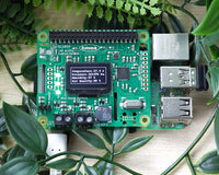
The Raspberry Pi Pico is a compact microcontroller based on the RP2040 processor - Raspberry Pi’s first in-house designed silicon. The RP2040 on the Pico uses 2 ARM processor cores, and also has 4 programmable IO controllers (PIO). These are like mini processors, and can help the Pico complete more complex tasks than it would otherwise be able to do. The Pico has 28 general purpose IO pins (GPIO), and 3 of these can also be used as Analogue inputs. The Pico can be programmed in several languages. The experiments in these resources are written in the Thonny Editor using MicroPython.
Pico Inventor's Kit Exp' 8 - Wind Power
Wind turbines convert the kinetic energy of air into electrical power. In this experiment the motor and fan are used in reverse to generate a voltage which can be measured and displayed by the Pico using a seven segment display.
- To generate a voltage by blowing on a fan blade to spin a motor.
- To measure this voltage by using an analog input pin on the Pico.
- To display the voltage generated using a seven segment display.
Video Walk-through:
Exp 8 - The Code
All experiments are coded in MicroPython in Thonny. To open in Thonny, copy and past the code below directly into the Thonny editor.
'''
Kitronik Inventor's Kit Exp 8

Control a seven segment display to show how much 'power' is generated from a 'wind turbine'
'''
import machine
import time
import math

# Setup the pins controlling the individual 7-segment display segments
segA = machine.Pin(18, machine.Pin.OUT)
segB = machine.Pin(17, machine.Pin.OUT)
segC = machine.Pin(16, machine.Pin.OUT)
segD = machine.Pin(15, machine.Pin.OUT)
segE = machine.Pin(14, machine.Pin.OUT)
segF = machine.Pin(13, machine.Pin.OUT)
segG = machine.Pin(12, machine.Pin.OUT)

pins = [segA, segB, segC, segD, segE, segF, segG] # Store the segment pins in a list for easy access

turbine = machine.ADC(26) # Setup the analogue (A0) on GP26 with a human-readable name

'''
This list of 10 numbers shows the states of the pins for the segments
to display the appropriate number. This is used to simplify the code
later - we can index the list to display the correct number.
'''
# numbers = [zero, one, two, three, four, five, six, seven, eight, nine, clear display]
numbers = [[1,1,1,1,1,1,0],
          [0,1,1,0,0,0,0],
          [1,1,0,1,1,0,1],
          [1,1,1,1,0,0,1],
          [0,1,1,0,0,1,1],
          [1,0,1,1,0,1,1],
          [1,0,1,1,1,1,1],
          [1,1,1,0,0,0,0],
          [1,1,1,1,1,1,1],
          [1,1,1,0,0,1,1],
          [0,0,0,0,0,0,0]]

clearDisplay = 10 # The position in the numbers list of the clear display setup

# This function takes in which number should be displayed, and then selects the correct pin/segment setup from the numbers list to control the output pins
def displayNumber(numberToDisplay):
    pin = 0
    for segment in range (7):
        pins[pin].value(numbers[numberToDisplay][segment])
        pin += 1

    return numberToDisplay

# Convert a value proportionally from one range to another
def scale(value, fromMin, fromMax, toMin, toMax):
    return toMin + ((value - fromMin) * ((toMax - toMin) / (fromMax - fromMin)))

displayNumber(clearDisplay) # Make sure the display is off

while True:
    # First read in the generated voltage
    generatedValue = turbine.read_u16()
    # Now we scale it to a much smaller range, as we only have a single 0-9 display
    # The ADC input ranges from 0 to 65535, but due to the voltage divider in the circuit, the maximum seen will only ever be 40000
    displayValue = scale(generatedValue, 0, 40000, 0, 9)
    # And finally display it
    displayNumber(math.trunc(displayValue))

    # Add a small delay so that the number doesnt change to rapidly to read.
    time.sleep_ms(100)
Inventors Kit Extra Resources:
Each of the ten experiments has been designed to ease you into coding and physical computing for the for the Raspberry Pi Pico. The experiments have been chosen to cover the key concepts of physical computing and they also increase in difficulty as you progress. This resource has been put together to provide additional information for this experiment and has not been designed to replace the booklet. The majority of the information you will need to perform and understand this experiment is contained in the booklet.
If you are new to coding and physical computing, even the least complex examples can be quite challenging. With this in mind, we created walk-through videos for each of the experiments. Our presenter talks you through the circuit in a way that backs up the information given in the booklet but in a style that some might find easier to absorb. As well as having a video walk-through, each page also contains the code. Although it is always good to tackle the code yourself, it can be handy for testing your circuit quickly. The code has been heavily commented as an extra learning resource. To get the most out of the experiment, once you've tested your circuit have a go at coding the experiment from scratch.
Follow the links in the table below:
| Exp No. | Experiment Name. |
|---|---|
| Digital Inputs & Outputs. | |
| Light Sensor & Analog Inputs. | |
| Dimming an LED using a potentiometer. | |
| Using a transistor to drive a motor. | |
| Control a servo with a potentiometer. | |
| Setting the tone with a piezo buzzer. | |
| Using a seven segment display. | |
| Exploring wind power. | |
| Capacitor charge circuit. | |
| Controlling ZIP LEDs. |
©Kitronik Ltd – You may print this page & link to it, but must not copy the page or part thereof without Kitronik's prior written consent.