"My name is Elsa Lily Novak and I have recently completed a period of 4 days’ work experience at Kitronik (8th-11th July 2019). I am a 17-year-old student studying at Redhill Sixth form and I really enjoy being creative. Designing and creating products that benefit the environment is my real passion and I believe that products can be designed, produced and packaged more ethically. Thus, I would love to go into a job that enhances these features of the design. If that job even exists! Kitronik produces inventive and engaging kits that make education a hands-on and fun experience whilst teaching some very complex electronics, engineering, and coding. Therefore, obtaining work experience in a design environment and having the opportunity to design this miniature fairground ride, using the high-tech facilities and tools on offer has been valuable. Additionally, I have received advice from highly qualified engineers and really got to understand and get a sense of the company’s ethos and intentions, allowing me to experience verstehen."
What we Need to Recreate this Miniature Fairground Ride
 The image of the blurred swing ride gave me inspiration for this project. Picture yourself in a fairground full of colourful flashing lights, fast-paced rides and the sound of humming motors. With this design, I have attempted to produce this exact atmosphere by creating a ring on top of a spinning tube. With this miniature ride, you can imagine yourself there without the long queues! This design used Kitronik’s products with everyday materials and tools that can be done at school.
Electrical Component List:
Tool Required:
- Pencil, Pen or Screwdriver
- Scissors
- Stanley Knife or Saw
- PVA or Glue Gun
- Course Sandpaper
- Electric Hand Drill
Everyday Material List:
- Corrugated Cardboard
- X2 Cardboard Tubes - One small enough to fit in the other
How I Made the Physical Model
Firstly, I sketched the design to plan where the crocodile clip wires would go by using a key of different coloured pens to represent the different wires involved. I then cut a large piece of cardboard from a packaging box with a height of 12.5cm and a length of 1.1m. I then applied glue to the 4mm end of the cardboard and attached both ends together to create a cardboard ring. I made a tray holder for the micro: bit, which was then glued onto the top of the tubing. I placed the micro: bit on a medium-sized piece of cardboard and folded the edges up to reach the micro: bit. I did this very roughly as precision was not required, and being larger than the micro: bit meant that it could be removed easily. If you observe the micro: bit, you can see that one side doesn’t have an overlap which means that the height of the side doesn’t matter. However, the other 3 sides have an overlap which needs to be visibly uncovered by the side of the tray for crocodile clips to be clipped on. So, bearing that in mind, I folded the sides up below the overhang of the micro: bit and cut the right height which should be roughly 2cm. I then cut in the places, as shown below, to create a flap to fold on the inside and glued it together. I cut the small inner cardboard tube (white) to 40cm. Cardboard tubes are spiral bounded, which means that they can be thicker which resulted in using a saw and a Stanley knife to cut out the shape of the motor, which had a height of 2cm and length of 3cm. Cutting the horizontal length out of the tube was the most difficult, so I tried to angle it to get around the corner and then sanded it down with sandpaper to make it flat so that the motor was flush to the tube. This enabled me to slot it in the tube and not stick out. I then attached the wheel which acted as the base of the tube. Next, I drilled 2 holes in the top of the tube (2cm from the top) and drilled down to the other side. These holes were designed to fit the skewers in, which were acting as spokes. I then lined the ring up and created holes in the cardboard with a screwdriver to slot the skewers in the holes. However, this wasn’t stable so I drilled a hole in the bottom of the tube above the motor slot and pushed a skewer in, which was cut to size, to add some structure and stability. Unfortunately, this didn’t resolve the issue.
  Therefore, I cut the tube (white) to 15cm, keeping the bottom end of the tube with the slot for the ground. I decided to get a larger tube that was sturdier and I applied glue to the top of the large tube (pink) and stuck the wheel on it in a fixed position for the motor. This attached the small tube also which allowed rotation on the motor axis. It sounds quite complicated explaining it but hopefully, photographs simplify it!
  Now that the base and tube of the design was stable, I attached 2 crocodile clips from the micro: bit down to the motor at the bottom of the small tube. I used 4 hexagonal lights which had holes for the crocodile clips, with labels that correlated to the labels on the micro: bit such as +V. The 4 LED hexagons were all connected which meant that I could wrap the wires around the skewers to then be in the right position for pushing in the cardboard ring near the skewer with a screwdriver.
How I Coded the Micro: Bit
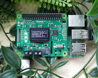
 This design contains a micro: bit which is essentially a small computer that appears as a circuit board. The micro: bit is given instructions via coding on a website called makecode.microbit.org. I have never coded before so this was my first time, but I found the micro: bit coding website relatively straight forward to use. Although, I kept the format on block form (on the left) which is more visual compared to the JavaScript option (on the right) which looks like the traditional coding format.
Features That Change at Compass Directions:

- I plugged the micro: bit in with a USB port by selecting the ‘Basic’ panel to find the ‘Forever’ block.
- In the ‘Logic’ panel a category called ‘Conditionals’ contains a block saying ‘if true then’ and I drag and dropped this into ‘Forever’.
- In the same ‘Logic’ panel, a category called ‘Comparison’ includes the block ‘0 < 0’, I drag and dropped this into the ‘if true then’ block twice. This took me a while to get in the correct position but you have to hover it over ‘True’ until it’s highlighted.
- I changed the numbers to 0 and 90. As at the exact 90-degree angle would mean that the colour will only appear at that exact position. Subsequently, 0‑90 gives a longer duration for the LED colour.
- I added ‘Compass Heading’ from the ‘Input’ panel into both blocks.
- Below and inside the ‘if’ block I put in ‘Pretty Lights’ from the ‘Klip motor’ to show the colour red when around the North compass axis. The micro: bit has rows of red LED lights and these can be programmed to light up in different patterns via the ‘Show leds’ from the ‘Basic’ panel. I put this below pretty lights in the ‘If’ block.
- Whichever square I clicked went white. This is where the light will come from, so I created an arrow pattern pointing up as North. I repeated all of these steps at East, South and West giving them different degrees, colours and patterns.
- I selected from the ‘Input’ panel the ‘On Button A Pressed’ block. Then I drag and dropped the turn motor block in the previous block.
- I set it as motor 1, forward at speed 25. It can withstand a spinning speed of 100mph for 3 minutes. However, in order to see the LEDs transition and the LED pattern, I decided to set it to 25mph for 3 minutes. I found from testing the design at varying speeds I could deduce the best-suited speed.
 As another feature, I programmed the motor to turn off when shaken if the micro: bit was to fall over. Completed by the ‘Input’ panel, block called ‘On Shake’.
- Then put in the ‘Turn Off Motor 1’ from the ‘Klip Motor’ panel.
- Finally, in the ‘Basic’ panel I selected the ‘On Start’ block.
- Then, from the ‘Basic’ panel, I drag and dropped the Set Pretty Lights to 0.
- But instead of the 0 section of Set Pretty Lights, I drag and dropped the block String of 4 Zip LEDs.
- I set it at 4 because I had 4 Hexagon LEDs.
- I selected the ‘Klip Motor’ panel to find ‘Pretty Lights Show Colour’ and put that underneath the previous block.
- I changed the colour to purple.
- Once I was happy with my coding, I clicked the big purple ‘download’ button at the bottom left to save the micro: bit file and download it on to the micro: bit. I could then unplug the USB cable and attach the micro: bit into my design.

Improvements
 From designing this product, I can reflect on any adjustments that would improve my design if I was to do it again.
- I would thoroughly plan the colours of the crocodile clip wires as, for instance, I have used 3 yellow wires in one section and it’s very confusing. However, I overcame this by noting down the specific shades of yellow and what they connect to.
- I would cut the cable ties to a shortened length or enhance them as intentional for the design.
- I would think of a way to conceal the crocodile clip wires. I could have designed an extremely complex design using the skills myself and the engineers had, however, the purpose was to reflect a design that could be constructed in a classroom. This way it’s more realistic in the time available (3 days for this design) and the purpose of the design. Therefore, hiding the wires and making it look neat and professional wasn’t the intention of this project.
Customisation
You could add seats at the end of the skewers for small figurines such as a doll in a handmade swing. You could also add patterns or colour to customise it or change the harsh straight lines of the string to a wavy or zig-zag pattern using scallop-edged scissors. Additionally, you could also change the coding to be different colours at each compass axis, or adjust the speed. A big 'Thank You' to Elsa for writing this blog!
©Kitronik Ltd – You may print this page & link to it, but must not copy the page or part thereof without Kitronik's prior written consent.