ZIP LEDs Experiment 10 for the ZIP LEDs Add-On Pack for the Kitronik Inventors Kit for the microbit. This experiment covers how to use a potentiometer to control the speed at which an LED spins around a ring. This experiment is not in the booklet and is only available online.

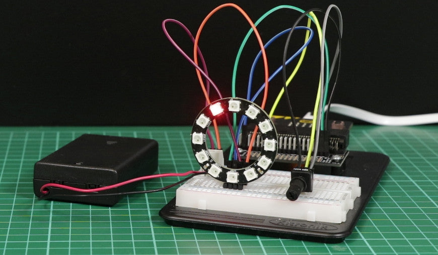
The Inventors Kit for the BBC microbit and the ZIP LED add-on contains all of the parts required for this experiment. It is possible to source the parts yourself but special attention should be given when powering the experiment. You will require two separate 3V power supplies. We recommend a 3 x AA battery pack for the ZIP LEDs. The BBC microbit should be powered separately, either via USB or with a 3V battery pack.
ZIP LEDs Experiment 10 – Using A Potentiometer To Control an LED:
In this experiment, firstly we light up a single LED and then we use a Potentiometer to control the speed that the lit LED spins around a ring.
Parts List:
- A BBC micro:bit.
- 1 x 3 AA battery pack.
- A ZIP Ring – 12 LEDs.
- 1 x Terminal Connector.
- A Potentiometer & Finger Adjust Spindle.
- 2 x Male to Male Jumper Wires.
- 5 x Male to Female Jumper Wires.
The Aims Of This Experiment Are:
- Learn how control ZIP LED colours.
- Also, how to move a light through any number of ZIP LEDs.
- And, how to control the speed of movement of an LED around a ring using a potentiometer.
Building This Circuit On The Prototyping System:
It is also possible to build the ZIP LEDs Experiment 10 circuit using the Prototyping System for the BBC micro:bit and the components listed at the top of the page. Once you have sourced the required parts you can follow the diagram below. However, if you have the Inventors Kit and the ZIP LED add-on pack, you will already have all of the parts that you require. As a result, you can get to work immediately.

Create the Following Code:
ZIP LEDs Experiment 10 was created using the Microsoft MakeCode Editor.
Microsoft’s MakeCode Editor is a drag and drop visual editor that provides a simple introduction to programming. Blocks snap together to build programs and are grouped by the type of function they do.
This experiment makes use of the NeoPixel blocks package in the MakeCode editor. Full details of how to add this package to the Editor can be found at the end of this resource.
What Will Happen:
The code will light up a single red LED, which will begin to move around the ring. In this case, rotating the potentiometer in either direction will affect the speed of rotation around the ring. An anti-clockwise turn will slow the LED and consequently, a clockwise turn will speed it up.
What’s Going On:

The microbit takes the analogue voltage from the pot and converts it to a digital value between 0 and 1023. The map block is used to convert this digital value to range that is suitable for our intended purpose. We settled on limits of a low of 1000 and a high of 100. The actual value that the Map block generates is stored in a variable we have named ‘Speed’. We use this variable as a delay in milliseconds between the movement of the red light from one ZIP LED to another. Therefore, the smaller the delay, the faster rate of movement.
The ‘rotate pixels by’ block ensures that the red light keeps moving around the ring.
Here is a step by step explanation of exactly what each code block is doing;
Start loop:

- In the first block, we set the number of LEDs to 12 and which microbit pin is being used and assign them to a variable called ZIPLEDS.
- The second block is to set the first LED at position 0 to red.
- Our third block then shows this LED, making it visible.
Forever loop:

- First of all, we create a new variable called ‘Speed’.
- The value that we are going to store in the variable is generated by a map block.
- The map block takes the analogue voltage input from the potentiometer connected to P1 and converts the analogue voltage to a digital value via the microbits ADC (which has a range of 0 to 1023) to whichever range we specify. You can see the values we chose in the above image.
- We then use the value that is in the ‘Speed’ variable as a pause value in milliseconds.
- The third block is to rotate the LED by 1 on to the next position. The speed at which the red LED moves from one LED to the next is determined by the ‘Pause’ value, which is influenced as a result of turning the Potentiometer.
- Finally, the fourth Block is to reshow the LED after it has been shifted to the next position.
Adding The NeoPixel Blocks Package To The MakeCode Editor:
ZIP LEDs experiment 10 makes use of the NeoPixel package. This is not added to the Menu as standard, but it can be added in a few mouse clicks.
![]()
1st Step: Click on the cog icon, highlighted in green in the above picture.
2nd Step: Select Extensions from the drop-down menu.

3rd Step: Once you’ve selected Extensions you will see a popup dialogue like the one pictured above. Click on the neopixel square and it will add Neopixel blocks to the menu (see below).
![]()