We show you how we made a custom light rig for time-lapse 3D print videos to ensure consistent results for each print. This is the conclusion of our short series of articles on creating time-lapse videos of 3D prints.

Whilst creating time-lapse videos of some of our recent 3D prints we encountered some difficulties getting consistent lighting. After trying a few different solutions we opted for designing a simple lighting rig that could be easily put on the printer when needed. What follows is a run down of the process we went through whilst creating the custom light rig. You will find a download link for our completed box design at the foot of the article.
Level Of Difficulty:
You Will Need:
You Will Learn:
- How to make a custom light rig for a Robox 3D printer.
- How to create a box using online tools.
- How to wire up and power the light kits.
Make A Custom Light Rig For Time-Lapse 3D Prints:
- Step 1 - Measure the size of the kits and the printer dimensions.
- Step 2 - Use online tools to create the box design.
- Step 3 - Import the design into your 2D design software and edit it.
- Step 4 - Laser cut the case.
- Step 5 - Build the electronics.
- Step 6 - Mount the electronics to the top panel.
- Step 7 - Build the box and glue it together.
Step 1 - Measurements:

We measured the Robox’s dimensions so that we could design the light rig to be central to the bed. Then we measured the size of the 3x3 Led Kits, we wanted to be able to spread them out evenly inside the case for more consistent lighting.
Step 2 - Using The Online Box Making Tools:

We used online tools to create a box design based on the dimensions measured in step 1. These online tools can automatically create the box for you, including joints. There is also an option to create the box with t-slots if you would rather build your box without using glue.
Export the created plans to DXF and import into your chosen 2D software.
Step 3 - Editing The Box Designs:

Once imported we added mounting holes for the PCB's and potentiometer, we also created an exit hole for power cable. Taking complete measurements during step one made this a quick and simple process.
Step 4 - The Laser Cutter:

Import your finished design into your laser cutter software and cut out your box design.
Step 5 - Designing The Electronics:

The above diagram details how we wired up the 3 x 5V Lamp kits to the 10KOHM potentiometer and the 5V power supply.
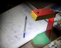
Step 6 - Mounting The Electronics:

The above image shows how we mounted the kits and the potentiometer to the top panel. Having the laser cutter make the holes is definitely a better proposition than drilling.
Step 7 - Build The Box:

Once everything is mounted you can then finish the box build, we've found that using plastic melt glue types makes for a solid and permanent join.

Download:
©Kitronik Ltd – You may print this page & link to it, but must not copy the page or part thereof without Kitronik's prior written consent.