Inventors Kit Experiment 9 Further Help. This resource has been produced to compliment the booklet provided with the Inventors Kit for the BBC microbit as a source of further information and hints and tips.

This further help resource contains download links for additional code examples and also a walk-through video that covers the experiment in full. The video also has hints and tips to help you complete the experiment.
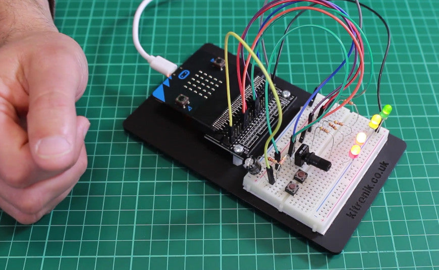
Inventors Kit Experiment 9 – Capacitor Charge circuit:
In this experiment, we will use the analog input of the BBC microbit to measure the voltage at the positive leg of a capacitor. A circuit will be created that allows the capacitor to be charged through a variable resistor (also known as a potentiometer.) The BBC micro:bit will be programmed to display the charge level of the capacitor both numerically and using external LEDs to create a colour coded display.
Video Walk-Through With Hints & Tips:

Code Downloads:
The code examples below have been individually zipped and can be downloaded by clicking on your preferred option. Once unzipped you can either open the and edit the code in appropriate editor or place the HEX file onto your microbit*.
MakeCode Editor & Python Code Downloads:
- This code was created with the MakeCode Editor, download the HEX file here.
- This code was created with the Python Editor, download the HEX file here.
Legacy Editors Code Downloads:
NOTE: The legacy editors will disappear at some undisclosed point in the future. The code can still be placed on a microbit and will run regardless but you won’t be able to use an editor. When that happens, switch to using one of the currently supported editors. We’ve already made the switch as the new editors are better and more fully featured.
- This code was created with the Touch Develop Editor, download the HEX file here.
* – To place the unzipped HEX file onto your microbit, connect your microbit to your computer via USB and then open File Explorer (Windows). Your microbit should show up as a removable drive. Simply drag and drop your HEX file onto the microbit in file explorer and the file will be transferred. The power light on the back of the microbit will start to flash, once the flashing stops the microbit is ready to run your code.
Kitronik Inventors Kit Resources:
| Exp No#. | Experiment Name. | Resource Type. |
|---|---|---|
| 1 | Say Hello to the BBC micro:bit. | Further Help. |
| 2 Pre V1.7 | Using an LDR and analog inputs. | Full Experiment + Further Help. |
| 2 V1.7 | Using a Light Sensor & analog inputs. | Full Experiment + Further Help. |
| 3 | Dimming an LED using a potentiometer. | Further Help. |
| 4 | Using a transistor to drive a motor. | Full Experiment + Further Help. |
| 5 | Using the accelerometer to control motor speed. | Further Help. |
| 6 | Setting the tone with a piezo buzzer. | Further Help. |
| 7 | Wind Power. | Full Experiment + Further Help. |
| 8 | Making a game using the compass. | Further Help. |
| 9 | Capacitor charge circuit. | Further Help. |
| 10 | Using an RGB LED. | Further Help. |
| 11 | Making a pedestrian crossing. | Full Experiment + Further Help. |
| 12 | Making a random dice. | Full Experiment + Further Help. |
Get The Kitronik Inventors Kit For The BBC microbit:
We do two versions of the Inventors Kit for the BBC micro:bit, with or without the BBC micro:bit included. Chose the option that is right for you from the links below.