This is a step by step guide for using free design tools to create 2D and 3D designs for 3D printing and is intended as an introduction to 3D design. The purpose of the design was to produce a resistor lead forming tool that would ensure that all resistors in a project were bent in an identical way, the perfect tool for those working on an electronics project that is going to be marked.

The designs and the printing were done by someone who is new to both, which highlights how easy it is to produce something usable using the highlighted tools. If you would like to print one right away you will find a link to the STL file at the foot of the article.
NOTE: Since we published this article Autodesk have discontinued all 123D Apps & products. They consolidated the tools and features of these Apps into key apps such as Tinkercad, Fusion 360, and ReCap Pro. You can get more information here.
An Introduction To 3D Design In 123D Design:
We chose to use 123D Design by Autodesk for several reasons; Schools can download it and use it for free, it has a much shallower learning curve than most commercial products and it is more than capable of the job in hand.

Level Of Difficulty:
You Will Learn:
- How to approach the design process.
- How to create a 2D design.
- How to turn a 2D design into a 3D model.
- How To export the design for 3D printing.
You Will Need:
The Process:
- 1 – The design aims?
- 2 - Taking physical measurements.
- 3 - Creating a 2D design that delivers our design aims.
- 4 - Using our 2D design to model our 3D object.
- 5 – Exporting the files and printing.
Step 1- Establishing the design aims:

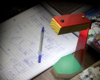
We wanted to produce a tool that allowed us to bend the leads of a resistor in a uniform way so that when they are placed on a PCB and soldered they all look the same, with the body of the resistor being centred between the holes. We wanted it to be easy to design and to also lend itself to being 3D printed without any issues. We tried to keep this firmly in mind through every step of the process. It also needed to be of sufficient length to be user-friendly. The rest of our design aims would begin to emerge once the physical measurements of a resistor had been obtained.
Step 2 – Taking physical measurements:
In order to produce the design we needed to know the physical dimensions of a resistor and decide what dimensions that the leads would be bent to. We broke out the Vernier callipers and measured every aspect of a resistor, noting down the measurements on a notepad as we did so. In most of our Electronic project kits, the holes on the PCB that the leads of a resistor go through are spaced 1.0 cm apart. To make the tool a little more useful we decided to design it so that it could be used for a variety of hole spacing’s; 0.7 cm, 0.8 cm, 0.9 cm, 1.0 cm, 1.1 cm and 1.2 cm. Before proceeding to the actual design stage we did a little research on google to get a rough idea of the look of commercial products. We found that our initial thoughts were in line with how designs for this type of tool were typically laid out.
Step 3 - Creating a 2D design that delivers our design aims:
After performing a couple of simple experiments in 123D Design we determined that the whole design could be sketched in 2D and then easily extruded out to make a 3D model. Every step of this 2D design process was carried out using various functions within the sketch menu as shown below.

The images below detail the order in which the various parts of the finished design were drawn in 2D. The area being drawn is highlighted, we’ve left the entire design in each image so you can see how it relates to the entire design.

The above image shows the centre section on which the resistor body will rest when the leads are to be bent, It was drawn as a rectangle and then the fillets were added to make it round at either end.

Then we drew in the sections that the resistor leads pass over before they are bent into shape, as shown above. We drew in some rectangles into the centre section to assist with ensuring that we placed these sections correctly. Although a resistors leads are approximately 0.5 – 0.6 mm thick we chose to make this dimension 1 mm wide so as not to stress the 3D printer too much.

The rest of the physical design was then added. At one end we created a method for allowing the tool to be hung up. With the sides, we ensured that the resistor leads had a small channel to help with bending them correctly and we wanted the whole tool to be of a size that made handling it easy.

The final 2D design step was to remove as many unnecessary lines as possible, this doesn’t affect the outcome but it does make it slightly easier to select the various areas for extruding. We chose to leave the centre line in as this would aid in ensuring that any text we add is centred.
Step 4 – Extruding the 2D design and adding text:
Extruding: We extruded the tool in three steps;

First the centre section was extruded by 3 mm.

Next, the resistor lead channel sections were extruded by 4 mm.

Finally, everything else was extruded to 5 mm.

Text: It can be quite tricky to get the text to print properly so the larger the text the better the result. We chose to make the text size 5 mm and Bold. The tool name and the ohm symbol were then extruded by 1 mm and the lead spacing dimensions were extruded by 0.2 mm. The extrusion values we chose were only just good enough to make a reasonable job of the text, there were still some minor issues but they weren’t severe enough to prompt a re-print. When placing the text we wrote in our text, selected a text size of 5 mm, formatted the text to be bold and rotated the text to ensure that it was facing the right way. Before clicking on ok
Step 5 – Exporting the files and printing:

The above image shows the process of exporting the 3D design in a format that can be used by a 3D printer. Make sure that you select to combine objects, this enables your printer to treat it as one object and not many objects that are very close together, even something as simple as this comprises a lot of objects and it may crash your printer software as it tries to work out how it is going to print so many objects so close together. Our 3D printer is a Robox and as such we use Automaker software to manage the print jobs. The printer will automatically detect what material we are using and inform Automaker which will then adjust the temperatures and print times accordingly. We usually go with the default print quality setting as this is usually adequate for most of our print jobs. If having the text print is a priority then going one better than the default will provide a better result.

After importing the STL file into Automaker we ensure that the model is laid flat on the bed and orientated in such a way that we can keep an eye on the print. You can see in the above image how we laid out the lead forming tool. Once printed you should have something that resembles our design shown below:

Download:
If your students tackle this or a similar project why not take some photos and submit them to our gallery via this email address:
gallery@kitronik.co.uk
©Kitronik Ltd – You may print this page & link to it, but must not copy the page or part thereof without Kitronik's prior written consent.


1 comment
Alex Leo
I have seen your work, It really good. I hope u continue to do good work.