A servo is a type of motor that is often used in robotics. The position of the motor can be controlled very precisely which makes it great for steering remote control vehicles and robots. Unlike a standard motor a servo requires a signal to tell the motor how far to turn. Most servomotors have a 3 wire interface. A red wire for the input voltage, a black wire for ground and a white or orange wire for the control signal.  The signal that controls the servo is a series of pulses, with the length of the pulses determining the angle that the servo will move to. If the signal is stopped the servo will lose its position. This is called Pulse Width Modulation, often shortened to PWM.
Learn how to:
- Connect a servo to a Picaxe control chip.
- Instruct a servo to make a loop of 90 degree turns.
Level of difficulty:
- Intermediate.
Parts List.
In order to control the servo you will need the following:
- Futaba S3003 servo.
- 8 pin PIC development board.
- PICAXE-08M2 chip.
You will also require the following equipment:
- Power supply
- Wire
- Picaxe software for programming the chip (free).
Controlling the servo.
The signal that controls the servo is a series of pulses, with the length of the pulses determining the angle that the servo will move to. If the signal is stopped the servo will lose its position. This is called Pulse Width Modulation, often shortened to PWM.

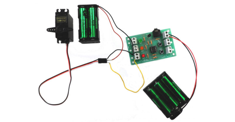
Connecting the servo.
A simple way to get your servo working is to connect it to a PICAXE microcontroller. The Kitronik PIC development board is ideal for this. Connect 6V to the red servo wire. Connect the output you wish to use to the white servo wire. Connect both the signal ground and power ground to the black wire on the servo. Use a separate power supply to power your PICAXE chip. Don’t panic if the servo moves a little as you connect the power, this is perfectly normal. Your servo should be wired up like the photo below.

N.B. The reason we use two separate power supplies is that the servo generates a lot of electrical interference or “noise” as it operates. This can cause the PIC timings to go wrong and the servo to not work properly.
Programming the servo
Now to program the Picaxe chip to send pulses to your servo. We’re going to take advantage of the Picaxe pre-programmed command for sending a pulse modulated signal to servos. This is called the ‘servo’ command and it takes the form: servo X, Y Where X= The output pin you want the chip to send the signal through. Y= The length of the pulses on a scale of 0-255 with 0 being the shortest and 255 being the longest.
Sample program
This simple program will move the servo position first to 90 degrees anticlockwise, then to the centre position, then 90 degrees clockwise and loops forever. The exact values for the servo command vary from device to device but the figures used below should give an approximation of what you should use.

Download a pdf version of this page here ![]() Learn more about the author read more »
Learn more about the author read more »