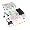
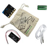
This Experiment Requires:
- BBC micro:bit. x 1
- BC337 NPN Transistor. x 1
- 2.2KΩ Resistor. x 1
- Terminal Connector. x 1
- Low Inertia Solar DC Mini Motor. x 1
- 3 x M/F Jumper Wires (if using the Prototyping System).
- 1 x Fan Blade.
- 5 x Crocodile Leads (if not using the Prototyping System).
The Aims Of This Experiment Are:
- To use a transistor to drive a fan motor.
- To control the speed of the motor using Pulse Width Modulation (PWM).
Experiment 4 Video Walk Through:
Experiment 4 Using A Transistor To Drive A Motor:
The output pins on most microprocessors can only supply a small amount of current, not enough for a power hungry device such as a motor. The BBC micro:bit is no exception to this. A transistor can be used to solve this problem. A transistor is like a gate for electricity, a small amount of current can be used to open the gate to let a lot of current flow through to power hungry components.Creating The Code Using The Microsoft Block Editor:
Below is an example of how to write the code for the experiment in the Microsoft Block Editor. If you're having difficulty producing your own code for this experiment, we've created the code for you that you can download directly from the embedded editor above..
Building This Circuit On The Prototyping System:
It is possible to build this circuit using the Prototyping System for the BBC micro:bit and the components listed at the top of the page, you can follow the diagram below.
Building This Circuit With Crocodile Leads:
 If you don't have the Kitronik Inventors Kit for the BBC micro:bit or the Prototyping System you can still build this circuit using the circuit diagram for reference and Crocodile Leads to join the components together. You can see an example of this in the picture below. When connecting the Transistor it is important to correctly identify the Base, Collector and Emitter leads. These can be seen in the picture to the right. Care should also be taken when connecting the transistor to ensure that there are no shorts, you should bend the pins away from each other before you connect the crocodile leads.
Circuit Diagram:

What Will Happen:
The motor should after a few seconds start to spin slowly, then faster until it reaches a maximum speed. At this point, will slow down and stop and the cycle will begin again.What's Going On (How Does It work)?:
If the transistor is turned on and off very quickly and it spends half its time on and half its time off then the fan motor will spin at half speed. By changing the percentage of the time that the transistor spends on (known as the duty cycle) the speed of the motor can be finely controlled. As the power pulses on and off and the width of the pulses are controlled, we call this process Pulse Width Modulation (PWM). The code works in two stages. The first loop writes the duty value to Pin P0 then increases the duty value by one and writes the value to P0 again. This repeats until the value reaches the maximum of 1023 (full speed). The second loop then kicks in and reduces the duty by 1 and writes it to P0 until the value reaches 0 (stopped). This whole cycle is inside a forever loop so the motor will speed up and slow down forever. The PWM output varies the duty cycle of the output voltage, as show below, to vary the speed of the fan motor.
Code Downloads:
The code examples below have been individually zipped and can be downloaded by clicking on your preferred option. Once unzipped you can either open the and edit the code in appropriate editor or place the HEX file onto your microbit*.MakeCode Editor & Python Code Downloads:
- This code was created with the MakeCode Editor, download the HEX file here.
- This code was created with the Python Editor, download the HEX file here.
Legacy Editors Code Downloads:
NOTE: The legacy editors will disappear at some undisclosed point in the future. The code can still be placed on a microbit and will run regardless but you won't be able to use an editor. When that happens, switch to using one of the currently supported editors. We've already made the switch as the new editors are better and more fully featured.- This code was created with the Blocks Editor, download the HEX file here.
- This code was created with the Touch Develop Editor, download the HEX file here.
Kitronik Inventors Kit Resources:
| Exp No#. | Experiment Name. | Resource Type. |
|---|---|---|
| 1 | Say Hello to the BBC micro:bit. | Further Help. |
| 2 Pre V1.7 | Using an LDR and analog inputs. | Full Experiment + Further Help. |
| 2 V1.7 | Using a Light Sensor & analog inputs. | Full Experiment + Further Help. |
| 3 | Dimming an LED using a potentiometer. | Further Help. |
| 4 | Using a transistor to drive a motor. | Full Experiment + Further Help. |
| 5 | Using the accelerometer to control motor speed. | Further Help. |
| 6 | Setting the tone with a piezo buzzer. | Further Help. |
| 7 | Wind Power. | Full Experiment + Further Help. |
| 8 | Making a game using the compass. | Further Help. |
| 9 | Capacitor charge circuit. | Further Help. |
| 10 | Using an RGB LED. | Further Help. |
| 11 | Making a pedestrian crossing. | Full Experiment + Further Help. |
| 12 | Making a random dice. | Full Experiment + Further Help. |
©Kitronik Ltd – You may print this page & link to it, but must not copy the page or part thereof without Kitronik's prior written consent.


13 comments
Jetro de Château
Your explanation in the video doesn't make much sense.You say the micro:bit cannot power the motor, but if you simply connect the black motor lead to 0V and the red motor lead to 3V the motor will start spinning. The transistor is not magically creating more power. What it does is modulate the power and you use the signal from pin0 for that modulation, using it as an automated on/off switch. I also had to manually add a “wait 20ms” block to each of the 2 while statements for the code to work. For best results, hold the motor in your hand so you can feel the vibration. Else it is really hard to notice the difference in PWM. Finally, to make things a little more visible you could use an If/Else/Else… structure to create a bar graph to display what level of PWM is being applied.
Euan
So if you could show how to make the code, so that it does what I wanted it to do in my first comment, that would be a great help. Thanks, Euan
Euan
Hi, I have tried to make the code so that the fan runs when it is plugged in, stops when it is unplugged. So the code is slightly different that what I am trying to do in my first comment than the code I have sent you. Thanks Euan
Mark Donnison
Hi Euan, if you send your code to mark.donnison@kitronik.co.uk I can have a look at it for you and give you some pointers.
Euan
Hi, I have been changing the code to try and make it so I press button A to start the fan, without pause, and to end press button B. I have not been able to change the code successfully. Any ideas? Thanks, Euan
Magnus Carlenäs
Hi! Can you explain to me why I should use the 2.2 kOhm resistor? I have students that is interested in the calculation of this. Can you provide me with an calculation example? Magnus (again)
Mark Donnison
Hi Magnus, there is the potential to damage the micro:bit. That's not to say that you will damage the micro:bit every time but you risk having the micro:bit operate outside of the range that it should operate in. For example, using a microbit to deliver power to a servo; you might get away with it 20 times in a row, but if it fails on go 21 you still have a destroyed microbit. Better to play it safe. For more detailed powering information, check this out; https://tech.microbit.org/hardware/powersupply/
Magnus
Hi again! Now I have tried to make a heat sensitive fan and it works very well: https://www.youtube.com/watch?v=iilfeimMDjM&feature=youtu.be I wonder though if there is a need for the transistor. Will the Microbit be damaged if I power it with P0 directly? I can get it spinning by connecting P0 to red and the black back to 0V and then make a program that starts when I digitaly write P0 to 1 and stop when P0 is set to 0. Like this: https://www.youtube.com/watch?v=qnF6cHEyTFc&feature=youtu.be The program: https://makecode.microbit.org/_f4cEvvMu1341
James Batchelor
Hi guys, One problem that you maybe storing up is that when you drive the motor via a transistor the motor, an inductive element, will produce a back emf. You can see this if you connect an led as a flywheel diode across the motor terminals. You can see a short flash of the led when you stop the motor. So I would suggest a 1N4001 or even a 1N4148 as a flywheel or overswing diode to protect the transistor. (Incidentally I crimped single connectors on the flying leads, simpler to insert than the screw terminals.)
Mark Donnison
Hi Magnus, the fan is just a motor with an impeller fan blade. Although you could use a digital write to turn on a motor you wouldn't have any speed control, it would be either on or off.
Magnus Carlenäs
Hi! I wonder if you have to use a PWM output to drive the fan or could I aswell use Digital write pin X to 1/0 ? I also have the motor board, I guess I could use the fan in the same way as I use a regular DC motor, could I use digital Write? I want to ask so I don´t damage the Micro:bit! Regards Magnus
Mark Donnison
Hi Paul, good spot. I'll update it as soon as is possible. Thanks again!
Paul Raftery
Hi, I've just purchased your inventors kit for the microbit and one of the first experiments I wanted to try was experiment 4 (using the motor + fan) as the temperature here in Bilbao is pretty hot at the moment. As I am learning python, I decided to download your python code to run the motor. Unfortunately your code didn't seem to work. I compared it to the block editor code and noticed that the python code is lacking the 10 ms delay. I added 'sleep(10)' to your micropython code and now it runs perfectly. Please could you update the code on your website. Good job with the kit. Thanks, Paul