The Zumo chassis is a great starting point for a buggy/robot project. In this tutorial we will show you how it can be used in conjunction with our Motor Driver board for the BBC micro:bit and our Klaw kit to create this fun buggy with gripper action!

Learn how to:
- Attach the Klaw kit to the Zumo chassis.
- Control the Zumo buggy with a microbit.
Level of difficulty:
- Intermediate.
In order to make your microbit controlled Zumo buggy you will need:

- BBC microbit.
- Kitronik motor driver board for the BBC microbit.
- Zumo chassis.
- Klaw kit.
- Top plate DXF file.
- 5mm Perspex Sheet for cutting the top plate.
- Connecting wire.
- micro metal geared motors. x 2
- 16mm M2 bolts. x 2
- M2 nuts. x 2
- 6mm M3 counter sunk screws length. x 2
- 12mm M3 counter sunk screws length. x 4
- 10mm M/F nylon spacers. x 4
- M3 nuts. x 4
- AA batteries. x 4
You will also need the following equipment:
- Soldering iron and solder.
- Computer and micro USB cable to transfer programs on to the BBC micro:bit.
- Small flat head screwdriver.
- Wire cutters.
- Small Philips screwdriver.
- Wire strippers.
Step by step guide to making a microbit controlled Zumo buggy
Step 1

Start by soldering two lengths of connecting wire to each of the two motors. Ideally about 15cm or longer. They can also be cut down in length later on if needed.
Step 2

Build the Zumo chassis as per it’s build instructions but do not connect the top plate included in the kit. Then, you should end up with a buggy that looks like this.
Next, solder a length of connecting wire to the two battery terminals as shown at the bottom of the image.
Step 3
The next step is to mount the Klaw gripper to the 5mm Perspex top plate (Cutting file here). Start by building the Klaw gripper as per its build instructions but do not connect the servo using the long M2 bolts or servo horn screw.

Then, place the servo against the top plate as shown above.

Then place the built Klaw on to the servo output shaft as shown above and secure using the servo horn screw.

Finally, secure the Klaw to the plate using the 2 x 16mm M2 bolts. These bolt through the servo, then through the mounting plate and into the Klaw holding all the parts tightly together.
Step 4

Now secure the M/F nylon spacers to the mounting plate (facing away from the servo) using four of the M3 countersunk screws.

Once complete the mounting plate should look like the picture above.
Step 5

The top plate can now be secured to the Zumo chassis. Start by feeding the two wires on each of the motors through the slots in the top plate as shown above. This will allow the top plate to sit down firmly on top of the motors. It can be easier to do this without the tracks in place.

Then remove the battery cover and screw the top plate to the Zumo chassis using the two short countersunk screws.

The last part of securing the top plate in place is to then bolt the front of it to the chassis. This is done using the remaining two sets of M2 nuts and bolts.
Step 6

The tracks can now be put back on the buggy and it should look as shown above.

Then feed the servo and motor wires between the M/F spacers and secure the motor driver board in place using the four nylon nuts.
Step 7

Feed the two power wires under the motor driver board and then connect them to the power terminal on the motor driver board. The back left battery terminal on the chassis is the positive output and the back right output is the negative terminal as shown by the red and black wires in the image above.
Step 8

Now the two motors need wiring in place. The left motor should then be wired to terminal P12 and P8, the right motor to terminals P16 and P0.
Step 9

The servo now needs wiring to the motor driver board. To do this the connector needs cutting off.

And the insulation also needs removing from the ends as shown.

The orange wire should then be connected to terminal P1 on the motor driver board.

Then the red wire should be connected to the Positive power terminal and the brown wire should be connected to the Negative power terminal as shown above. The wires have also been fed under the PCB for neatness.

Any excess cable can now be tidied away under the PCB.
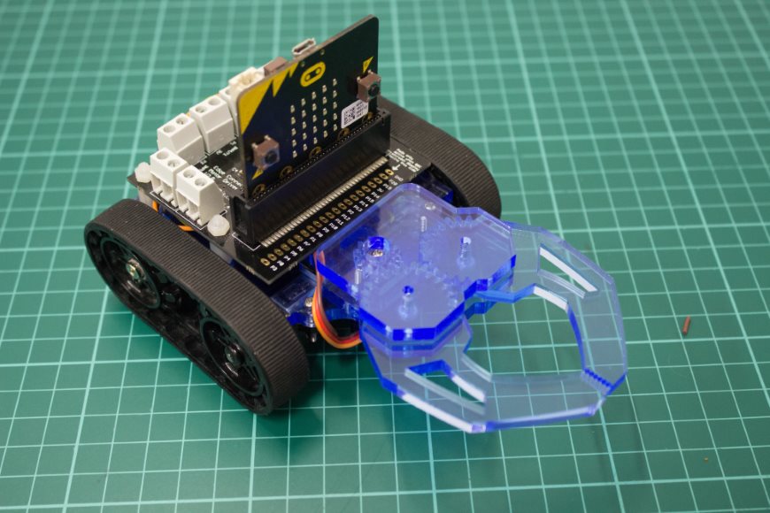
Step 10
With the BBC micro:bit inserted the buggy will look like this.
Testing
To allow you to test the buggy we have created two .hex files. One is for the BBC micro:bit that controls the buggy. The second file then allows another micro:bit to act as a wireless controller. The buggy is controlled by tilting this control microbit and the buttons on the microbit are used to control the Klaw gripper.
Try it out! Below are links to two .hex files.
Helpful hints
If the motors turn the wrong way check the way in which they are wired to the terminals. The code can be altered to match your setup as required.
Find more information on how the motor driver board works here.