Experiment 10 from the Inventors Kit for Arduino. In which we explore using an RGB LED. Included in this resource are code downloads, a description of the experiment, and also a video walkthrough. It provides additional help and is not meant to replace the documentation that ships with the kit.  Arduino is an open-source code-able electronics platform. The boards can process inputs from many sensors, and also control outputs such as LEDs and motors. The Arduino is controlled by the code with which it is programmed. This code is written in the Arduino programming language, using the Integrated Development Environment (IDE). Once complete, the code is easily transferred to the board using a simple USB lead.
Inventors Kit for Arduino – Exp 10 Using An RGB LED:
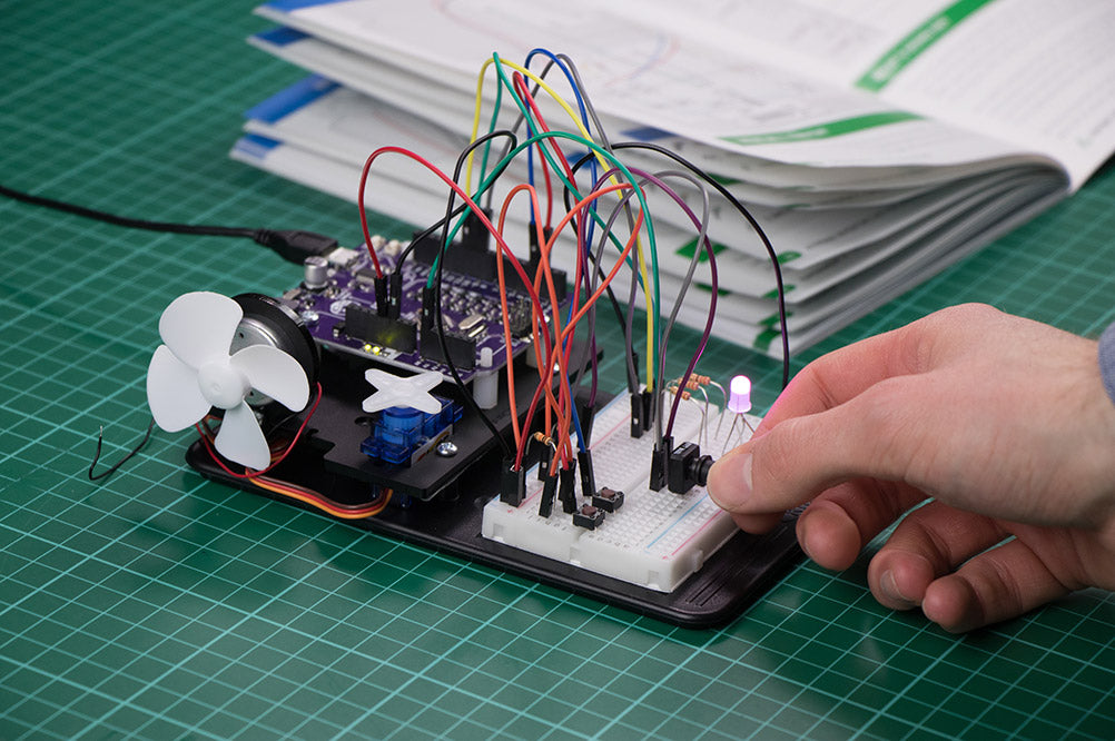
This experiment puts the RGB LED to use. An RGB LED is a special LED that contains three separate LEDs in one package. As you might have guessed the three LEDs are Red, Green and Blue. The light from these LEDs can then be mixed together to allow for the creation of many colours. We can use the PWM outputs of the Arduino to have a very fine control over the colours and also shades. The RGB LED included in this Inventor’s pack is a common cathode LED which means all three LEDs inside the package share the same negative leg. The aims of this experiment are:
- To use an RGB LED.
- And also to observe how different colours are made from mixing red, green and blue light.
Video Walkthrough:

Exp 10 Code:
Either open a new Sketch (File > New) then create the following code by typing in the editor window. Or, click the open code button in the editor to open the code in the online editor.
Inventors Kit Extra Resources:
Each of the ten experiments has been designed to ease you into coding and also physical computing for the Arduino. The experiments have been chosen to cover the key concepts of physical computing and they also increase in difficulty as you progress. If you are new to this, even the least complex examples can be quite challenging. With this in mind, we created walkthrough videos for each of the experiments. Our presenter talks you through the circuit in a way that backs up the information given in the booklet but in a style that some might find easier to absorb. As well as having a video walkthrough, each page also contains the code. Although it is always good to tackle the code yourself, it can be handy for testing your circuit. The code has been heavily commented as an extra learning resource. To get the most out of the experiment, once you’ve tested your circuit have a go at coding the experiment from scratch. Follow the links in the table below:
| Exp No#. | Experiment Name. |
|---|---|
| Digital Inputs & Outputs. | |
| Light Sensor & Analog Inputs. | |
| Dimming an LED using a potentiometer. | |
| Using a transistor to drive a motor. | |
| Control a servo with a potentiometer. | |
| Setting the tone with a piezo buzzer. | |
| Using a seven segment display. | |
| Exploring wind power. | |
| Capacitor charge circuit. | |
| Using an RGB LED. |
Hola, compré el kit, me gustarías saber si hay una versión digital del manual en español o para poder traducir.
Quedo atento.
Saludos
Marcelo Poveda, docente
Santiago, Chile
Hi,
Thank you for getting in touch.
Unfortunately, at the moment we do not have a digital version of the manual available in Spanish, nor do we have an official translated version.
Apologies that we cannot assist with this on this occasion.
If you have any other questions regarding the kit, please don’t hesitate to get in touch and we’ll be happy to help.