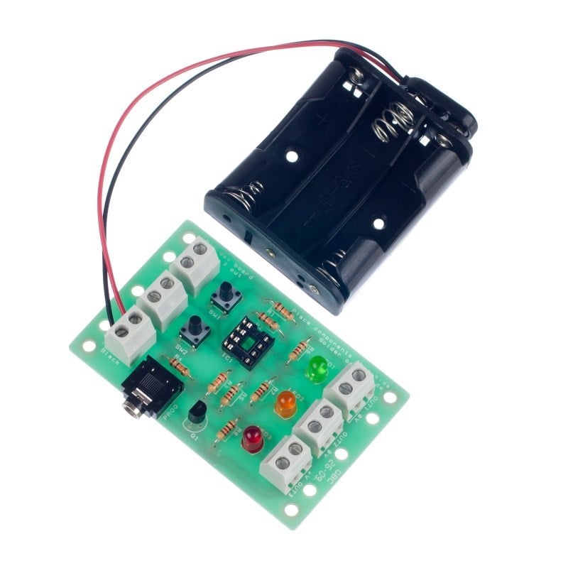
This board has been designed to complement the smaller project board.
This larger development board (once built) can be used as a starting point for a project by attaching inputs and outputs to the board via the terminal blocks.
The PIC software can then be developed and the complete solution tested without using a soldering iron. Once students are happy with their design they can transfer the design to the project board, soldering their chosen peripherals into the board. This development board can then be reused on future projects.
Processor not included.
Features:
- This board is compatible with most education Flowcharting Systems.
- Connect any device to the outputs of the board including LEDs, sounders, motors etc.
- This development board can then be reused on future projects.
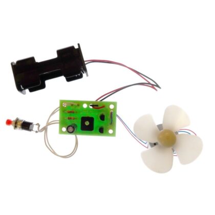
- The teaching notes for this project include a number of possible projects including, a decision maker, traffic light, timer, quiz buzzer, alarm and a timed fan.
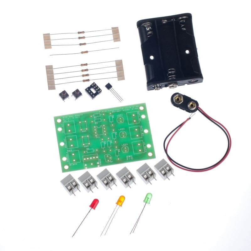
Contents:
- 4 x 1KΩ Resistors.
- 3 x 10KΩ Resistors.
- 1 x 22KΩ Resistor.
- 1 x BC337 NPN Transistor.
- 2 x 6mm PCB Mount Tactile Switch.
- 1 x 3.5mm PCB Mount Jack Socket.
- 6 x Two Way Terminal Blocks.
- 1 x 8 Pin IC Socket.
- 1 x Heavy duty PP3 Clip Lead.
- 1 x 3AA Battery Cage with Clip.
- 1 x Red Low Current LED
- 1 x Green Low Current LED
- 1 x Yellow Low Current LED
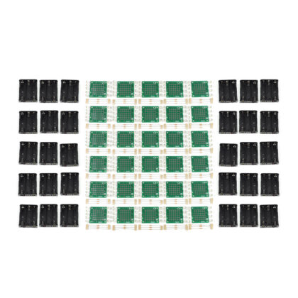
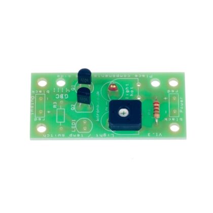
- 1 x PIC development board PCB
Dimensions:
- PCB Length: 76mm.
- PCB Width: 48mm.
Requires:
- Your choice of processor (PICAXE or GENIE).
- You will also need either the PICAXE or GENIE programming software and lead.
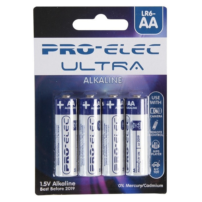
- 3 x AA Batteries.
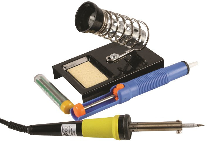
- Soldering Iron.
- Solder.
- Wire Cutters.
Resources:
Note:
- This kit requires soldering.
- Processor not included.
- You will also need either the PICAXE or GENIE programming software and lead.
Reviews
There are no reviews yet.