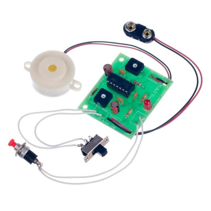
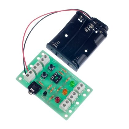
The timer project uses a dual 555 timer, which once started by pressing the button illuminates an LED until the desired time out period has elapsed when a buzzer is sounded.
The duration of both the delay and buzzer sound period can be determined by the student and are easily adjusted by PCB mounted potentiometers. This allows the board to be used for a variety of applications, such as an egg timer or a timer for a game (Max time period 200 seconds, max buzzer period 10 seconds).
Features:
- Adjustable delay and buzzer sound.
- Maximum time period: 200 seconds.
- Maximum buzzer time: 10 seconds.
Possible Applications Include:
- Egg timer.
- Timer for game.
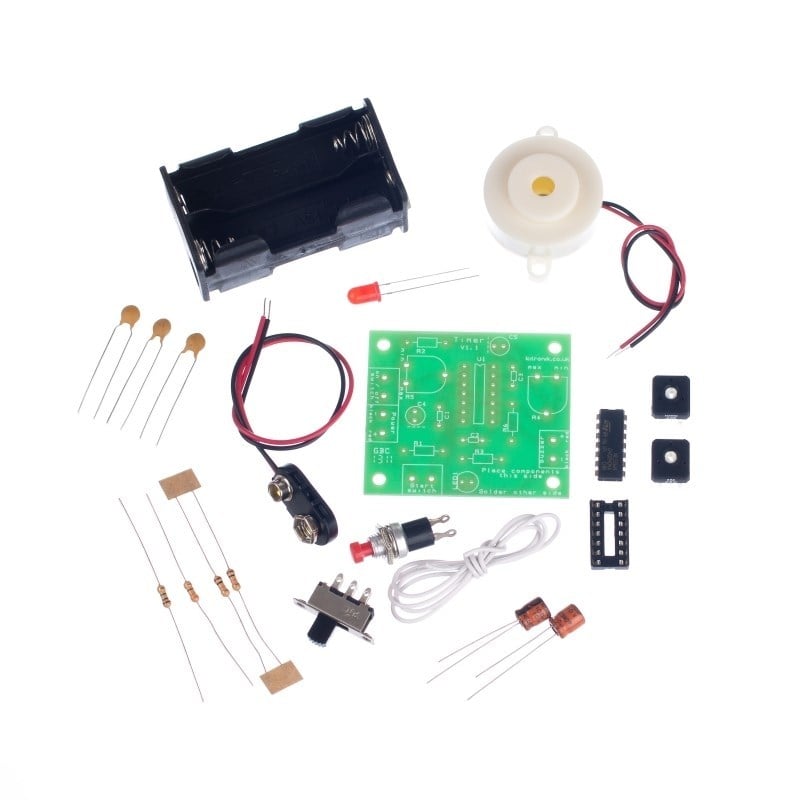
Contents:
- 1 x PP3 Battery Clip Lead (Heavy Duty).
- 1 x 4xAA Battery Cage with Clip.
- 1 x Miniature DPDT Slide Switch.
- 1 x Miniature Push to Make Switch, Red.
- 1 x NE556 Dual Timer IC.
- 1 x IC Socket 14 Pin.
- 1 x Piezo Buzzer (with Drive).
- 3 x Capacitor, Ceramic, 50V, 10nF.
- 2 x 100uF Cap Low Leakage.
- 2 x 10KΩ Resistor.
- 1 x 1MΩ Resistor.
- 1 x 330Ω Resistor.
- 1 x PCB trimmer 100k POT.
- 1 x PCB trimmer 1M POT.
- 1 x Red 5mm Diffused LED – 275mCd.
- 1 x Timer Project Kit PCB.
Dimensions:
- PCB Length: 54mm.
- PCB Width: 46mm.
Video:
Requires:
- 4 x AA Batteries.
Resources:
This kit is supplied in a simple grip seal bag.
Reviews
There are no reviews yet.