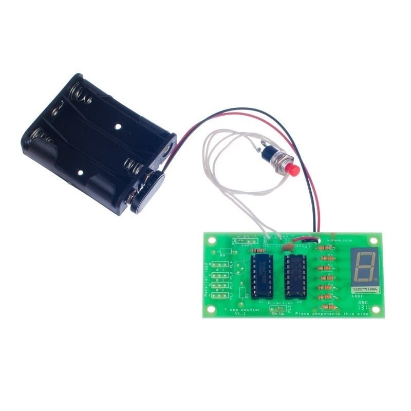
This kit uses a binary up-down counter IC and a binary to 7-segment display driver IC to operate the 7-segment LED display. Connections to the board allow up or down counting to take place and pre-set value to be loaded.
The kit makes a nice table football scoreboard as supplied or an electronic dice if used in conjunction with the square wave generator (Application note available).
Features:
- Connections to the board allow up or down counting to take place and pre-set value to be loaded.
- The kit uses both a Binary Up/Down Counter IC and a Binary to 7 Segment Display Driver IC.
- Press the switch to count the LED display up/down.
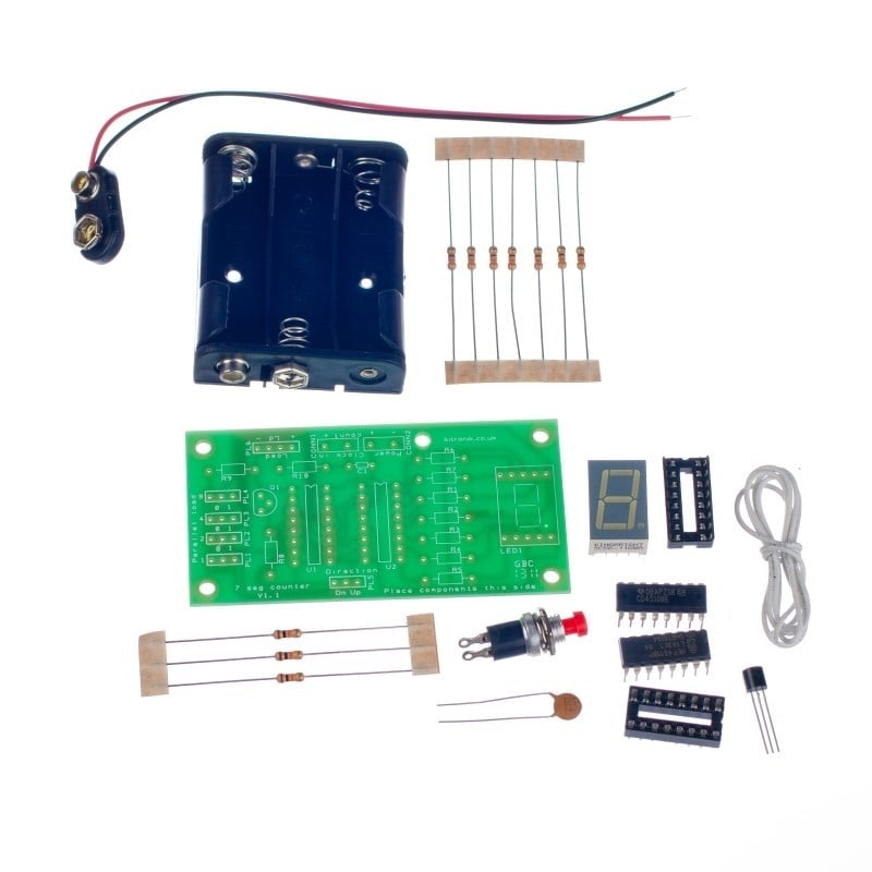
Contents:
- 1 x 4510B BCD Up / Down Counter IC.
- 1 x 4511B BCD To 7 Segment Driver IC.
- 2 x 16 Pin IC Holder.
- 7 x 330Ω Resistors.
- 3 x 10KΩ Resistors.
- 1 x BC337 NPN Transistor.
- 1 x 100nF Capacitor, Ceramic.
- 1 x 7 Seg Display Module Green.
- 1 x Push To Make Switch.
- 1 x PP3 Clip Lead.
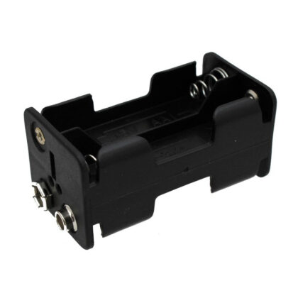
- 1 x 3AA Battery Holder.
- 0.5m Connecting Wire
- 1 x 7 Segment Display PCB
Dimensions:
- PCB Length: 85mm.
- PCB Width: 44.5mm.
Requires:
Resources:
Note:
- This kit requires soldering.

Reviews
There are no reviews yet.